

For optimal performance, ensure all connections are secure and corrosion-free. Regularly inspect battery terminals and check for loose wires, as these can lead to power disruptions.
Pay attention to the functionality of control modules, as they are crucial to the operation of numerous components. Software glitches or outdated firmware can hinder overall system performance; updating software as needed is advisable.
Monitoring the condition of fuses and relays is essential. Replacing any blown fuses and testing relays can prevent further complications and maintain uninterrupted service.
Keep an eye on the charging system, particularly the alternator’s output. A malfunctioning alternator can lead to insufficient power supply, affecting various electrical components. Regular testing can identify potential failures ahead of time.
Lastly, consider the integration of sensors and wiring harnesses, as they play a key role in system communication. Inspect these components for wear and tear, as damaged sensors can lead to improper readings and erratic behavior.
Diagnosing Battery Problems in Today’s Vehicles
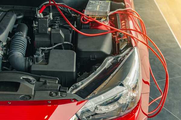
Begin with a visual inspection of battery terminals for corrosion and secure connections. Corroded terminals can impede the flow of electricity, leading to starting difficulties. Use a multimeter to check the voltage; a healthy battery should measure around 12.6 volts or more when the engine is off. If the reading falls below 12.4 volts, consider charging the battery. Conduct a load test while the engine is running; a voltage drop below 13.5 volts indicates potential alternator failure.
Listen for unusual sounds when starting the engine, such as clicking or grinding, which often signal a lack of sufficient power from the battery. Keep an eye on dashboard warning lights; the battery or charging system light may illuminate when problems arise. Regularly check your battery’s age; most have a lifespan of 3 to 5 years, and older units are prone to failure even with proper maintenance. Replacement may be necessary if problems persist after testing and cleaning.
Identifying Faulty Wiring and Connector Issues
Begin by visually inspecting all wiring harnesses for any signs of wear, fraying, or chafing. Check the insulation closely to detect any breaks that could result in power loss. Use a multimeter to confirm continuity, ensuring the circuit operates correctly.
Connectivity is key; ensure all connectors are firmly seated and free from corrosion. Corroded or loose connections can lead to intermittent faults. Cleaning connectors with contact cleaner can restore proper function.
- Look for burnt areas around connectors, indicating overheating.
- Examine any solder joints for cracks or cold soldering, common areas to fail.
If you experience erratic behavior from electrical components, trace the wires back to their source. Pay attention to sharp bends or areas where wires may rub against other components, leading to wear and potential shorts.
When testing, utilize a wiring diagram specific to the car model. This ensures you are tracking the right circuits and pinpointing problems accurately. Compare readings across the expected values in your reference material.
- Document every step to maintain a clear diagnostic process.
- Consider replacing sections of wiring that show significant degradation rather than only addressing the symptoms.
Addressing Failure in Automotive Sensors and Modules

To enhance diagnostic accuracy, prioritize regular sensor calibration and ensure firmware updates are performed as recommended. This practice minimizes errors stemming from outdated software and maintains alignment with vehicle manufacturer specifications.
Routine inspection of wiring harnesses and connectors is crucial. Corrosion or fraying can lead to signal disruptions, making thorough checks during maintenance visits non-negotiable. Replacements should be made using OEM parts to maintain system integrity.
Utilize diagnostic tools to track sensor performance metrics; this data provides insight into any underlying faults. Focus on parameters such as voltage output and response time, allowing for proactive identification of components at risk of failure.
Finally, establish a practice of logging sensor data over time. This information plays a significant role in recognizing patterns that may indicate impending module issues. Keeping a robust electronic record aids in anticipating necessary repairs and reduces the likelihood of unexpected breakdowns.